
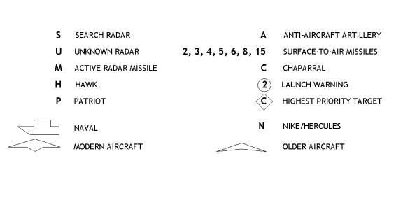
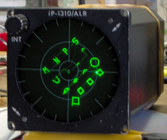
The Radar Warning Receiver (RWR) is part of a threat warning system. If you’re familiar with Falcon 4.0, the RWR display is the 3 inch diameter screen just under the left glare shield. It categorizes and prioritizes radar-emitting threats. The closer a threat symbol is to the center, the greater the indicated threat. Based of the radar pulse signature, the RWR will identify the threat as being a search radar, or a particular type of missile guidance radar, and so on. It displays a unique symbol for each threat type.
The angular position of the symbol relative to the center is an indication of the threat’s azimuth relative to the F-16’s heading. You will also see or hear the RWR display referred to as an azimuth indicator.

picture courtesy of Jay Fagner.
Goal: Make It Work with Falcon 4.0
Jay Fagner, Martin Ingold and I have decided to see if we can make a real azimuth indicator (pictured above) work with Falcon. We’re working with very limited data. No manuals. No schematics. Just enough basic info to power the display and see a spot on the screen. We have been told that the display works with vector graphics data, but not particularly well with raster* graphics, apparently because of inadequate intensity .
Why do this? Because it would be really, really neat? Because it was there? Because we have too much time on our hands? Let me know if you figure it out.
(*Raster is what your TV and CRT computer monitor do. Vector displays draw by guiding the beam they same way you guide a pencil when drawing.)
DIY Vector Graphics Generator
Step one is to build a vector graphics generator. Fortunately, the library of standard threat symbols is small. There are only about 20 symbols, and they are all limited in size. We can store the instructions on how to draw the symbols within the graphics generator. That way we won’t have to send a large amount of data each time we need to draw a symbol. We simply send a single byte that identifies which symbol is needed, and a few more bytes to describe where to draw the symbol on the screen. Further, because the symbols are small, we need only use 8 bit arithmetic to draw them. All in all, it looks like the performance required from a graphics generator is quite modest.
My earliest hands-on experiences with computers involved punched cards. (I miss them. They made great bookmarks.) So I occasionally look at computer products today and am amazed with the incredible strides that have been made.
This project caused another such moment when I started looking at options for the graphics generator. Out of curiosity I made some rough estimates of the graphics performance available from a PIC micro controller and found (to my amazement) that a $7 micro controller was probably up to the task.
[21 May 2005] Of course design inflation occurs here are it does anywhere else. The above list of symbols is the original Falcon 4.0 set. The current set is somewhat larger. The thought now is that we will implement perhaps 32 basic symbols and make a potentially larger set of more complex symbols by combining two or three basic ones.
Some Vector Graphics Background
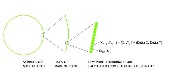
Vector graphics computers generate symbols from a collection of straight lines. (Curves are actually made of a sequence of very short straight lines.) Lines are themselves made one point at a time. The basic line drawing algorithm is to add incremental values to the (X, Y) coordinates of the current point’s position to calculate the successor point’s coordinates.
Using PIC instructions, it takes 13 steps per point (including the loop overhead) to calculate the successor coordinates when line drawing. A PIC running at 20 MHz executes one instruction every 4 clock periods, or every 0.2 microseconds. So the PIC could generate a point every 2.6 microseconds.
If we estimate that we need to redraw the complete screen every 20 milliseconds (that’s a 50 Hz refresh rate) to avoid flicker, a PIC could generate up to 7,700 points. Let’s knock that down to 7,000 points to leave time for fetching data and initializing the loop. The RWR only displays the 16 most hazardous threats, which means each symbol can consist of an average of 437 points. If the points are 0.01” apart, we have 4.37” of line length on average per symbol, which should be more than adequate.
Not too shabby for $7.
Some Vector Graphics Hardware
Here’s a block diagram of the graphics generator. You’ll notice that it has two pairs of DACs. These are digital to analog converters that take an 8 bit digital value from the PIC and convert it to an analog voltage. There are two pairs because this design separates the drawing of the symbols from the positioning of them. Drawing requires arithmetic. Positioning does not. If we combined drawing and positioning, we would have to do 16 bit arithmetic on an 8 bit micro controller. This would be slooowwww.
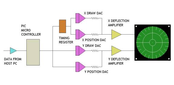
A command from the host PC to the graphics generator is of the form, “draw symbol #N at location X, Y”. We don’t have to do any arithmetic with the location values, simply load them into the position DACs, and get busy drawing the lines that make up symbol #N.
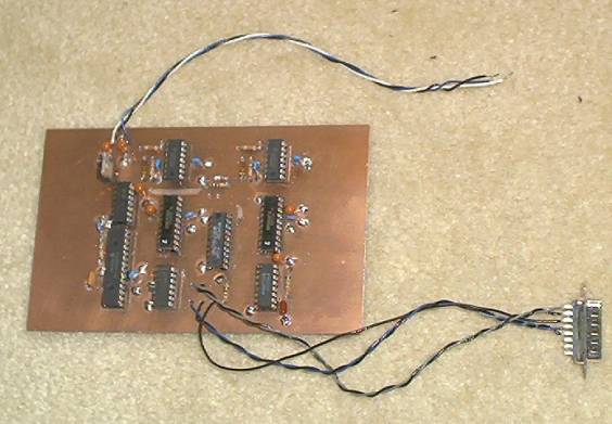
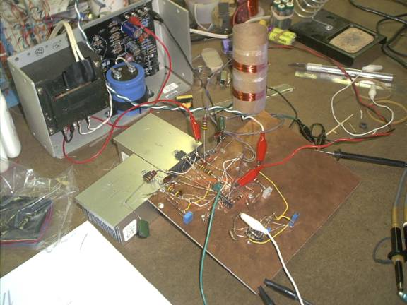
[8 June 2005] Here's a picture of a portion of the graphics generator prototype. It has the micro controller and DACs, but lacks the deflection amplifiers. Nonetheless, this is enough to test the communication and drawing functionality. The output can actually be viewed on an oscilloscope that supports X-Y mode
[18 October, 2005] The graphics processor is working, as is the majority of the firmware. The symbol library is more or less there. The relative sizes of the symbols may be off, but the symbols display properly. Here are a few pictures of the symbols being displayed on an oscilloscope.


There are a few extraneous dots because I'm not using a blanking pulse to turn off the beam when not actively drawing symbols. This is something we plan on doing with the real RWR display.
Deflection Amplifiers
[14 December 2005] The X and Y deflection amplifiers must output current that is proportional to the voltage produced by the graphics generator DACs. We need current outputs because of the way the electron beam in the display is controlled. The beam deflects in proportion to the strength of the magnetic fields generated by the deflection coils. Strength is proportional to current. Hence, we must control the current to control electron beam movement.
Most power amplifiers are voltage-in, voltage-out devices. We can't simply connect such an amplifier to a deflection coil. The coils are both inductive and resistive. This means coil's magnetic field strength will not vary in proportion to the voltage applied to it.
The trick is to place a resistor in series with the coil and use it as a means to sense the current through the coil. This works because the current through a resistor is directly proportional to the voltage across it. We can use the voltage from this sensing resistor as a feedback signal to adjust the voltage from a power amplifier to just the right value so we get the proper current regardless of the deflection coil inductance and resistance.
Another amplifier requirement is that it has to provide differential outputs. If we vary the voltage on one end of the coil to cause 200 milliamps to go in, we must vary the voltage on the other end of the coil to cause 200 milliamps to come out. This is because the centers of the deflection coils are internally connected to +28 volts to support the image centering adjustments. (More on this setup at the end of the page.)
These requirements make the deflection amplifier design somewhat challenging, but having spent 16 years at university I am up to it. (My extended time there was spent in technical pursuit. Contrary to what you may have heard, the coeds in the Fine Arts Department had absolutely nothing to do with it.)
Or me.
The following picture is of a (more or less) working prototype of one deflection amplifier. The two power chips bolted to the aluminum squares are 30 watt amplifiers. The squares are convenient scraps I pressed into service as temporary heat sinks. The large resistors just below the power amps are 4.7 ohm resistors used to sense the current through the coils. The chip under the red clip is a quad opamp.

[3 January 2006] I'm in the process of replacing the metal scraps with a couple of surplus CPU coolers. The power amps need to dump a fair amount of excess heat and my rather informal approach to heat sinking just isn't doing enough. Also, I've added a small triangle and square wave generator to the board so the prototype will have a built in test signal source.
[12 January 2006] Well, the amplifier appears to be behaving itself now. The larger heat sinks are in place and may be a bit of overkill. Turns out most of the heating was from a nasty high frequency oscillation. Once that was tamed, thing cooled down a fair amount. The amp also required some tweaking to speed it up. The version above was taking about 300 microseconds to settle, far too slow. The version below is better than 95% settled within 5 microseconds.
This version was built using TDA2050 power amplifiers. They don't have quite the voltage rating needed for this application. I have some LM1875's on order. They're a little more robust.
RIP
A few of the parts that gave their all for this project.

Building a More Robust Test Article
We're getting close to making a PC board that pulls all the pieces together. This is a draft layout which is sure to contain errors, but I'm sure Jay will find them before we commit to having one made. We need to build a new test version that can be put through its paces. The firmware is in need of some tweaks. I suppose some documentation describing the programming interface would be a good idea, too.

The Circuit Boards Are Here
[1 April 2006] Jay got a pair of boards made for the project. Because of size limitations imposed by his version of the layout software, he split the circuitry across two boards rather than placing everything on a single one like the layout study above. He also produced an aluminum box that both protects the boards, and acts as the heat sink for the four power amplifier chips that make up the deflection coil drivers.

I am hopeful that RL will relax a bit and I can get this cooking in test mode shortly.
[9 April 2006] The logic board is working. Some mislabeling on the schematic caused a small assembly err, easy to correct. A visual check on the amp board revealed a small silk screen error, also easily correctable. Got the dummy load for the second channel made. Biggest time sink has been excavating the work bench to find room to work.
[14 April 2006] Both boards are now working when connected to the test inductors used to simulate the IP-1310 deflection coils. I've made a number of component value tweaks and will likely make a few more. I had power on the IP-1310 for the first time a day or so ago. It works as expected.
Unfortunately, when the IP-1310 is connected to the deflection amp, things Do Not work as expected. There is a nasty oscillation.
RL requires that I set this aside for a few days. Back later.
[19 April 2006] The oscillation continues to be a beast. I can bludgeon it down, but the overall amplifier performance suffers. From a design perspective, the amplifiers should be well behaved and reasonably fast. In a SPICE simulation, the amplifier has loads of phase margin. (A magic phrase from the world of the engineering priesthood. Phase margin is good to have.) Our implementation seems to be a bit short somehow.
[23 April 2006] The bulk of the oscillation problem was traced to opamps being operated outside their recommended parameters. So the SPICE sim was correct for as far as it went. It was used to model the linear circuit operation. The opamps were being pushed into non-linear regions, something not being modeled.
At this point we can throw symbols on the screen. There is some overshoot in the amps that distorts the symbols a bit. We'll either tweak that out, or add some delay in the firmware to minimize its impact. We still need to get the blanking signal working. That will remove the faint lines connecting the symbols as well as the bright dot on the corner of the right most square.
The amplifier has accumulated a number of changes during debugging. Most have been component value changes, but a few involved cutting the foil and changing the circuit.

[28 April 2006] I revised the symbol library so the symbols appear vertical. The original library was put together for a display having horizontal and vertical deflection. The IP-1310 has diagonal deflection. Haven't a clue why. Originally I thought I would do a little analog matrix-ing of the deflection signals to create a 45 degree rotation. Then I thought better of it. Doing the rotation in analog hardware adds complexity, not much, but some. Revising the library is just a pain in the butt, then it's over. Anyway, here are the results:

These are the first 16 symbols in the library. In total there are 32 symbols. More complex symbols are made by combining these basic symbols. Generally, this means putting a circle or diamond around a number or letter. There's also a little caret that can be placed over a symbol.
So what's left? Well, I have to boost the amplifier gain so the symbols can be positioned anywhere on the screen. Right now the gain is restricted and only the center portion of the screen can be written to. I'll probably tweak the amplifier compensation a bit more. Compensation is a trade-off between speed and stability. And I'll likely play with the blanking a bit more. I'm feeding a TTL logic signal into the display, and it's apparently okay. However, video signals are typically 1 volt. TTL swings closer to 5. I may be over driving the display video input.
[8 May 2006] The gain has been tweaked so that symbols can be positioned farther from the center of the screen. Looks like we can easily get 16 basic symbols on screen at any one time. Threat symbols may be made of more than a single basic symbol. For example, placing a diamond around a symbol indicates it to be the highest priority target.
I experimented with smaller blanking voltages. Turns out that a 1 volt video signal doesn't do a very good job at blanking. The 5 volt TTL logic signal looks like the way to go.
PIC Firmware
One of the very nice features of the PIC micro controller used here is that it supports the use of subroutines. This allows a hierarchical approach to be taken that greatly simplifies the coding. The "main" level of the firmware need only be concerned with reading the display list generated by the host. It doesn't have to draw anything. It only sets up the conditions for a subroutine to begin the drawing process.
The following flowchart is an overview of that main level code. Each box represents a variable number of associated assembly-level instructions. The yellow boxes are executed only when power is initially applied, or when the host PC sends a reset command. The dark blue box is an "idle loop", a short sequence of instructions that occupies the PIC while it is waiting for for the beginning of the next drawing cycle. The light blue boxes are the steps the PIC executes as it traverses the host generated display list.

One might think that a routine called "DRAW_SYMBOL" actually would do a bit of drawing. In fact, it only has the task of seeing that a symbol is drawn, not doing any drawing itself. It fetches the description of how to draw a symbol. Since a symbol is a collection of lines, the description is a collection of line descriptors. DRAW_SYMBOL sets the stage for another routine, DRAW_LINE, to actually draw a single line out of the set of lines that make a symbol. It repeats this process until it has caused DRAW_LINE to draw all of the lines that make up the symbol. When it is done, it returns.

DRAW_LINE is the routine that actually gets the fun of drawing. It is very simple and can only draw a single line. It is simple because simple is fast, and fast is what is needed.
There is one subtle point about drawing on a vector graphics display. You don't want the beam turned on when it's not moving. The beam intensity must be set high enough to make a bright line when it is moving. If it is turned on and not moving, it makes a very, very bright stationary dot which at minimum is distracting, and may very well be strong enough to damage the phosphor coating on the screen. So the beam is normally blanked (turned off). As DRAW_LINE has the responsibility for moving the beam, it also has the responsibility for turning the beam on and off. The first thing it does when called is turn the beam on (i.e. un-blank), and the last thing it does before returning is turn the beam off.

These three chunks of firmware take care of the key functionality, drawing. There are two additional chunks that play important support roles.
The first stores the data that describes how to draw each type of symbol. It is simply a 2 dimensional array implemented as a collection of PIC tables.
The other chunk is the interrupt service routine that manages the data link with the host PC, and a timer internal to the PIC. The data from the PC is simply the display list that tells the PIC what symbols to draw and where to place them on the screen. The internal timer sets the redraw interval. To maintain a constant brightness, the symbols must be redrawn at constant intervals. The timer keeps the drawing process on track.
Some Info About the RWR Display
The voltage outputs from the DACs are amplified and applied to the RWR display (aka, azimuth indicator). The display is a magnetically deflected CRT, much like (non-lcd) computer monitors, though smaller. A beam of electrons is squirted against the back of the phosphor coated faceplate, which makes a spot on the faceplate glow. Current through deflection coils on the sides of the CRT create magnetic fields that bend the electron beam, and so move the glowing spot. It’s the voltages from our amplified DACs that create the currents in those deflection coils.

[2 November 2005] After many hours of following printed circuit board traces, we now have a fair idea of how the IP-1310ALR display works. The deflection coils are wired to the rear connector on the display. The surprising thing is that the coils are also wired to the +28 volts DC connection. This provides the means to supply a bias current to each winding so the center point of the generated image field can be aligned with the center point of the display's reticule.
So the bottom line is that we will need to drive the deflection coils in a differential manner from current sources that can handle the 28 volt connection.
