

Trade paperback binding
Building Simulated Aircraft Instrumentation is not available in any format.
I have no plans to do another printing. There are too many things I would like to improve, add, or change. If there's enough interest and if I ever manage to complete the books I'm currently working on, I may consider a second edition.
Please do not email me asking if I have an old copy or know where one might be found. Sorry, but I do not.
Book overview
Building Simulated Aircraft Instrumentation is an in depth introduction to making functional "steam gauge" style engine and flight instruments for use with recreational flight simulators. It describes in detail how air-core movements, servos, and stepping motors work, and illustrates through projects how to use them to simulate A/C instrumentation.
This is a hands-on book. Although there are a few engineering descriptions, it is primarily through the projects that the different simulation approaches are demonstrated. The projects were chosen to illustrate a range of simulation techniques. Each project is documented with complete mechanical drawings, electronic schematics, and if a micro controller is used, with a commented firmware listing.
This is a book for flight sim hobbyists, but realistically, the content tends to above average complexity. Building a simulated aircraft instrument requires a variety of skills including metal working , the ability to construct electronic circuitry, and a touch of assembly language programming. That said, the metal working is limited to cutting small flat pieces of sheet aluminum and brass, drilling holes and making a very few, simple bends. The circuitry can be built on perf-board, and the key knowledge about assembly language is how to download and run the free assembler from Microchip. The assembly code is included in the book.
If you were in a bookstore holding a copy of the book, you could thumb through it for a bit more detail, and read a few paragraphs to judge the writing style. Since you aren't, take a look at the following chapter descriptions, and read a sample chapter (PDF).
Chapter overviews
Air-Core Movements
Air-Core Movements is an in depth description of the mechanism used in a great many automotive and marine tachometers, speedometers and fuel gauges. This is a simple, robust movement that can swing the needle in a number of different simulated A/C instruments. The chapter covers the capabilities and limitations of the movement, as well as, describing methods of electrically driving it.
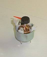
Air-Core Construction
Air-Core Construction is a guide to building an air-core movement using readily available materials. There is certainly no reason you couldn't use a commercially manufactured unit, but they are not normally retail items and may be hard to find in small quantities. Generally they are sold in quantity to other manufacturers who use them in their products, like cars. In any case, building an air-core movement can be a satisfying endeavor, and this chapter tells you how.

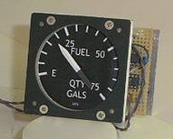
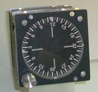
Air-Core Airspeed Indicator
Air-Core Airspeed Indicator builds on the previous chapter by adding analog electronics to drive the air-core movement. Well, it's nominally analog. I tossed in a few logic elements, but it's still mostly analog and does not require programming a micro controller. The operation of the circuitry is covered in detail. You get the schematic, a block diagram and a couple of pages explaining how it works.
This chapter also provides an introduction into the general mechanical construction of all the simulated instrument projects. The approach is simple, consisting mostly of making straight cuts and drilling holes. Additionally, the method of providing internal instrument lighting is detailed.
You probably noticed the picture is one of a fuel gauge. I actually prototyped the project as a fuel gauge, but decided the book needed an ASI more. Fact is, this project can be any single pointer type indicator you desire.
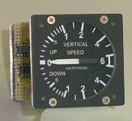
Air-Core Vertical Speed Indicator
Air-Core Vertical Speed Indicator is the last chapter in the air-core section. It presents the design of digital electronics to drive an air-core movement. It is based on a PIC micro controller, and interfaces to the host PC through an RS-232C serial com port. The circuitry is pretty simple, consisting of three chips, four if you count the voltage regulator. Most of the project's complexity in is the firmware. There are several pages providing an overview, because, while the assembly listing is commented, it's nice to have a rough idea of what's going on before diving into the thick of things.
Servo Principles
Servo Principles opens the section on servo-based instrument simulations. The servo approach is frequently used in both flight-rated and commercially produced simulator instruments. Servos come into their own in applications requiring the movement of relatively large indicators, like the horizon in an attitude indicator.
The chapter overviews RC servos, presents a one-chip RC servo tester, and lists a number of RC servo sources. It covers the inner workings of an electromechanical servo loop, and presents a few rules of thumb for adjusting a self-made servo loop. The remainder of the chapter provides useful information about some of the (electro-) mechanical odds and ends that often are needed in servo loops: motors, potentiometers, shafts, bearings, bushings and gears.
Servo Turn Coordinator
The Servo Turn Coordinator chapter puts a pair of RC servos to use moving slip and roll indicators. The project electronics is basically analog in nature, and does not require programming a micro controller.

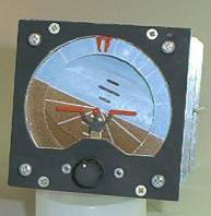
Servo Attitude Indicator
The next chapter, Servo Attitude Indicator, uses a pair of RC servos to simulate the type of gyro horizon instrument you might see in a non-aerobatic, general aviation aircraft. This is the most mechanically complex project in the book. There are several sheet metal components that must be bent, though nothing extraordinary. There are no electronics included in the chapter as the project can make use of either the analog circuitry of the previous chapter, or the digital circuitry in the following one.
Servo VOR/GS CDI
Servo VOR/GS CDI wraps up the servo section. RC servos are used to move the two needles. As a concession to mechanical simplicity, the observed and back course bearing indicators make use of seven-segment LED displays. While there is more circuitry in this project than any other, it is straightforward. It just takes a little longer to build. The chapter introduces the rotary encoder, describing it in some detail. It also shows how to drive seven-segment displays using a micro controller and a few low cost components.(Sorry for the wretched picture. Need to get one with the seven-segment displays visible.)

Stepping Motors
Stepping Motors opens the third section. It describes hybrid and can stack motors, two types of stepping motors quite useful in simulating instruments. It covers full stepping, half stepping and micro stepping. It discusses motor acceleration and deceleration. Finally, it presents several circuits for electrically driving stepping motors.
Stepping Motor Gyro Compass
Stepping Motor Gyro Compass demonstrates how to use a relatively high resolution stepping motor (400 steps per revolution, in this case) to make a direct drive gauge or instrument. The high torque of the motor makes it a good match to the relatively high mass of a compass card disk, but there is nothing to prevent using this approach for any single pointer style gauge. The chapter introduces the optical interrupter as a sensor to indicate the zero position of the compass card disk. The electronics portion of the project is based on a micro controller.
Stepping Motor ADF/ RMI Head
Stepping Motor ADF/RMI Head expands on the previous chapter by using two motors to drive a pair of concentric indicators. For an ADF or RMI head, one indicator is a compass rose disk and the other is a pointer. The basic mechanism can be used for a dual pointer style gauge such as a helicopter rotor and engine tachometer, or an engine oil temperature and pressure indicator. The chapter includes drawings for both a 3" ADF/RMI head, and a 2" oil temperature and pressure gauge. The motors used are smaller, lower resolution (24 or 48 steps per revolution) units. A few gears boost the effective positioning resolution so the indicators move smoothly. The electronics portion is micro controller based.

The red glow here and below is from the LED faceplate illumination. You can use whatever color appeals (green LEDs for NVIS, for example). Looks REALLY cool with the room lights off.
Stepping Motor Sensitive Altimeter
Stepping Motor Sensitive Altimeter is another example of what can be done with a high resolution stepping motor and a handful of off-the-shelf plastic gears. The altimeter's three pointers are coupled through these gears to give them a 1:10:100 speed ratio. The electronics is micro controller based.

Stepping Motor Turbine Tachometer
Stepping Motor Turbine Tachometer shows that a stepping motor based gauge doesn't have to have micro controller electronics. This project is actually an analog servo type gauge that uses a ten turn potentiometer for position sensing and feedback, and a smaller stepping motor to swing the pointer. But this isn't just a single pointer gauge; it has a second pointer in the lower right portion of the faceplate. The second pointer displays the units digit. This project is modeled after a gas producer N1 tachometer.

Interfacing
Interfacing is an introduction to interfacing between the book's projects and flight simulation software running on a Windows OS computer. An in depth coverage of the topic is outside the scope of the book, but this is an important topic. The projects don't function if not driven by the simulation software. This chapter provides an overview of the interfacing process, listing a number of recreational flight simulation possibilities (Microsoft Flight Simulation isn't the only one), provides some thoughts on needed programming skills, and offers a simple design for a port expander that supports multiple projects on a single com port.
Appendices
Included in the appendices is a tutorial on doing very accurate layout of the flat parts for the projects. There are lists of sources of parts, and sources of additional information. There are dimensioned drawings of standard panel cutouts for one, two and three inch instruments.