
The Servo Approach
The servo approach is a tried and true technique used in both simulated and flight-rated instruments. Basically there is some sort of motor (often a DC motor, but nothing says it cannot be an AC unit) that moves the output indicator (pointer, compass rose, horizon, etc.) often through a gear train. A sensor of some sort (often a synchro transmitter in a flight -rated instrument, and a potentiometer in a simulated one) tracks the position of the output indicator and feeds this position information back to servo controller electronics. The controller electronics compares the actual position with the desired position then generates a voltage which causes the motor to move the indicator toward the desired position.

This picture above shows a basic servo with a small electric motor, a gear train, and a position sensing potentiometer on the output shaft. (That's the dark gray cylinder in the back). The green thing represents the electronic circuit board. (I ran out of drawing energy when it came time to make the ICs, resistors, and other fiddly stuff). This is more than just random, made-up illustration. It's actually very close to what's really inside RC servos.
Using RC Servos
RC servos are rotary actuators used in the radio controlled car/airplane/boat/robot hobbies. They are made by a variety of manufactures and range widely in size, price, and capability. Servos with metal cases and ball bearings approach $100US. These are high performance units with capability far in excess of what's needed for a simulated instrument. Tower Hobbies markets a standard size, standard performance model with plastic case and bushings. It goes for about $9~10US, moving it within an attractive price range. RC servos are readily available through Ebay, as well.
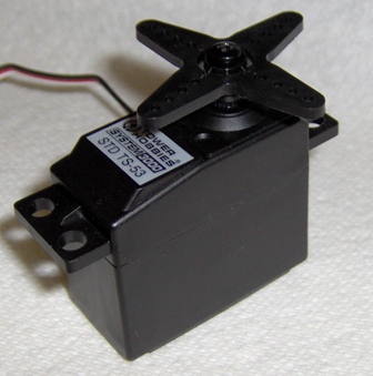
RC servos are controlled by a varying pulse width signal, easily generated by a micro controller. If you already have an analog control voltage coming from an interface card in your PC, this varying width pulse can be generated by simple circuitry based on something like a '555 timer chip. (Check the robot hobbyist sites. They list quite a few circuits for driving RC servos, as well as having instructions for modifying servos.)
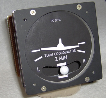
RC servos are very fast moving, capable of moving through its full range in several hundred milliseconds. Full range, however, is limited to 180 degrees. These servos look attractive for simulating turn coordinators, artificial horizons and pointer style instruments requiring less than 180 degrees of movement. While certainly they could be used for other instruments, this would require additional gearing making them a little less attractive in those applications.
If you are interested in using gears on the output of an RC servo, a few high-end hobby sources (like Robot Zone) sell gears with interior splines that match the splines on the standard-size servo output shaft.
A turn coordinator is easy to make using a pair of standard size RC servos. One rocks the wing while the other moves the ball.
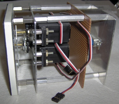
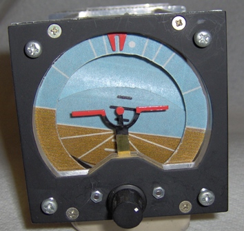
An attitude indicator is somewhat more complicated, but not terribly so. There is more mechanical construction, but it still comes down to a pair of RC servos pushing a few bits of painted metal around.
Using motorized potentiometers
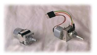 Another
servo-related item you might consider is a motorized potentiometer. It's
a small motor and gear train slip coupled to a potentiometer. These
items were widely used in remotely controlled audio systems. I think
newer audio systems take another approach today, but motorized pots are
still available. As opposed to the 180 degree limit on RC servos,
motorized pots will swing through 270+ degrees. However, this full
range is not completely usable. The construction of the pot is such
that the extreme ends of the resistance element where it ties to the
terminals is within this 270+ degrees. These means you have to turn the
pot's shaft a significant amount before you see much change in the
resistance. Ultimately, these pots offer about 190~200 degrees of
rotation with sufficiently linear resistance change to be useful in this
application.
Another
servo-related item you might consider is a motorized potentiometer. It's
a small motor and gear train slip coupled to a potentiometer. These
items were widely used in remotely controlled audio systems. I think
newer audio systems take another approach today, but motorized pots are
still available. As opposed to the 180 degree limit on RC servos,
motorized pots will swing through 270+ degrees. However, this full
range is not completely usable. The construction of the pot is such
that the extreme ends of the resistance element where it ties to the
terminals is within this 270+ degrees. These means you have to turn the
pot's shaft a significant amount before you see much change in the
resistance. Ultimately, these pots offer about 190~200 degrees of
rotation with sufficiently linear resistance change to be useful in this
application.
Surplus items pop up for about $4US (try All Electronics and Electronic Goldmine). New items are available in the neighborhood of $10US (Digi-Key). Pretty much all you need to do to make a gauge based on a motorized pot is put a pointer on the shaft and configure a basic servo loop controller. The controller can be based on classic analog circuitry with op-amps, or (of course!!) you can use a micro controller. Motorized pots are geared to make remote control operations like volume adjustment easy, so they are rather slow. It can take several seconds to traverse the pot's entire range. This makes a gauge based on one most suitable for slowly varying measurements like fuel quantity and manifold temperature.
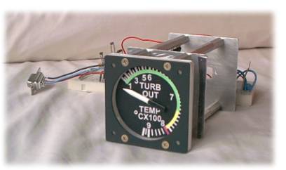
This temperature gauge is based on a surplus 20K motorized potentiometer picked up mail order from Electronic Goldmine for $3.50US. You can see the proto board peeking out from behind it, testimony to its incomplete nature. This prototype works reasonably well. It is PIC controlled and responds to host commands communicated over a serial port. The PIC determines the pot's position by using a timer to measure the period of a '555 oscillator having the pot as a frequency controlling element. The period of oscillation is linearly related to the resistance. Given that the pot is more or less linear, this period measurement provides adequate position feedback on the pointer position.
I should mention that the scale on this prototype is really too large an arc for the useable linear range for the particular motorized pot used. That's really too bad because the mechanical construction of a gauge using a motorized pot is very simple and easy to make.
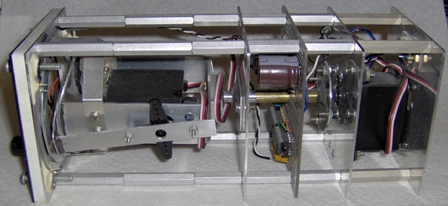
These two approaches are not the only possibilities for servo-based simulations. It's quite reasonable to build servo systems from scratch. This is less convenient, but allows you the latitude to tailor the system performance. Although the earlier servo examples make use of DC motors, you might want to consider stepping motors used as an AC motor. They have substantial torque at low RPM so a lower gear ratio would be required, reducing the mechanical complexity.
Potentiometers remain excellent choices for sensing the position of the indicator. If you're building from scratch you can use multi-turn units to get beyond the typical single turn pot limitation of roughly 270 degrees.