
DTS v2.0 & An Interesting New Book (29 December 2007)
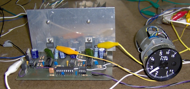
I'm well on the way to building a prototype of a revised Digital-To-Synchro converter. The parts cost has dropped by roughly $30, the resolution has increased slightly to 13 bits, and the data connectors have been added to the board. I've stayed with a single sided board layout even though it requires several jumpers. The single sided layout can be built easily with DIY printed circuit board kits. It's easy enough to use the single sided artwork as a starting point for a double sided board should some enterprising individual wish to employ the services of a commercial board house.
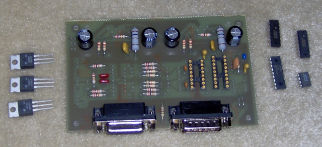
I still have a bit more soldering to complete the prototype. I'll leave off the power amps for the initial testing. Most of the testing is in verifying the computer to DTS communication and proper functioning of the micro controller code and associated scaling circuitry. Once that's working, the power amps are just a bit of icing on the cake. Of course, before I can do that, I have to revise the micro controller code as well as the host driver code.
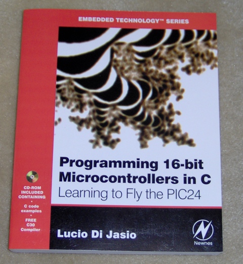
I limit the number of technical books I buy these days. It's too easy to get sucked into long, dark side alleys for weeks at a time. Besides, after years and years of not limiting my purchases, room to put the damn things is at a premium. Nonetheless, this one caught my eye, and somehow it magically appeared on my desk.
I haven't taken the time to more than leaf though it, but I'm impressed with the progressive approach the author has taken in developing this tutorial.
DTS Revisited (22 December 2007)
It's looking more and more like a DTS revision is a worthwhile idea even though it means a significant reworking of a "completed" chapter. I ordered a couple of LTC1590 12 bit MDACs directly from the manufacturer using their prototyping quantities ordering service. The parts came yesterday. On the plus side, one $7.50 part replaces two $17~22 parts, and a few circuit mods allow me to improve performance as well. On the down side this requires a new circuit board layout, new firmware, new host software, building another prototype, and new chapter text describing circuit operation.
(The DTS or "Digital To Synchro" project is a key system component needed to use some sorts of real aircraft instruments in a flight simulator.)
DTS Revisited (12 December 2007)
A trend in electronics is the continuing reduction in the size of parts. This trend means hours of audio can be stuffed into an MP3 player smaller than a box of matches. It also means that we older flight sim hobbyists with our somewhat less than perfect eye sight and maybe just a little bit oversized fingers face a real challenge when it comes to building DIY electronics. Those surface mount components are tiny!
I design the projects for the upcoming book 2 with ease of construction in mind. One problem is that electronics parts are increasingly available only in super teenie weenie surface mount packages. This restricts what I can choose for parts. So far I've been reasonably successful in selecting parts that can be seen with the naked eye.
Unfortunately, one of the key parts used in the DTS (digital to synchro) project has seen its price almost triple since I prototyped it. I'm concerned this may mean the part is in short supply. I don't want to publish the book then find no one can build the project because the parts are too expensive or just plain not available.
I've found an alternate part which is a dual version of the original part. This is good as the DTS uses two of the original part. The alternate costs less, can be ordered directly from the manufacturer(!) in small quantities, and is available in a standard 16 pin plastic DIP package. Further more, it's also available in a surface mount package with the same pin out. This means that if the big package is discontinued, there is at least a possibility of using the surface mount package with an adapter on the PC board designed for the large package.
So, that's what I'm doing right now: revisiting the DTS project and deciding if a re-design should be done.
Back from FanCon (19 November 2007)
Well, I'm back from Seattle and the 2007 AVSIM FanCon flight simulation convention. Nice to put a faces to a few names. My presentation went reasonably well. Attendance was fair considering it was the first slot Sunday morning; the peak crowds come on Saturday. Anyhow, I had a nice little crowd of friendly listeners who posed some good questions.
I seem to vaguely remember I was writing a book on flight simulation. Guess I'll dig around on my desk and see if I can find anything resembling a manuscript.
AVSIM FanCon Presentation, Odds & Ends (17 October 2007)
At least a few of the house projects are done; we finished the rain gutters literally minutes before the rain began. College has cranked up again so the house is a bit quieter. I'm slowly getting back into the flight sim world.
Mostly, that means finalizing the presentation I'll be giving at AVSIM FanCon 2007. There are a few pictures that could be improved, but it's pretty much there. The handout is in draft form, need to add a bit more detail.
And then... back to the book.
Still Working on the House (31 August 2007)
For the most part I'm still in maintenance mode, cleaning up old house projects and tweaking the web site. Giving some thought as to where to begin when I can again focus on the book.
Not Much Sim-Wise (10 August 2007)
Well, the first major house project is just about complete. A few pieces of trim and some paint should wrap it up, then on to the next.
Presenting at AVSIM FanCon 2007, Summer & an Interesting NASA Book (13 July 2007)
I've managed to draft a tutorial presentation for the November AVSIM convention in Bellevue, Washington. It's tentatively titled "Ditching the Keyboard - A DIY Approach to Using a Real Landing Gear Switch with Microsoft Flight Simulator X". I emailed Matt Johnson, who's coordinating the presentations for AVSIM, and received the encouraging news that AVSIM is interested in having me present. Guess I had better finish it.
Summer has finally happened: kids home from college, the refrigerator empties three times as fast, hot water for showers has to be scheduled, grandparents have visited, other grandparents have been visited, daytime temperatures occasionally spike over 100F, I've got house-fix'n projects to do, etc. Book 2 is probably stuck at 75% for awhile.
I made a surprising find at our public library:
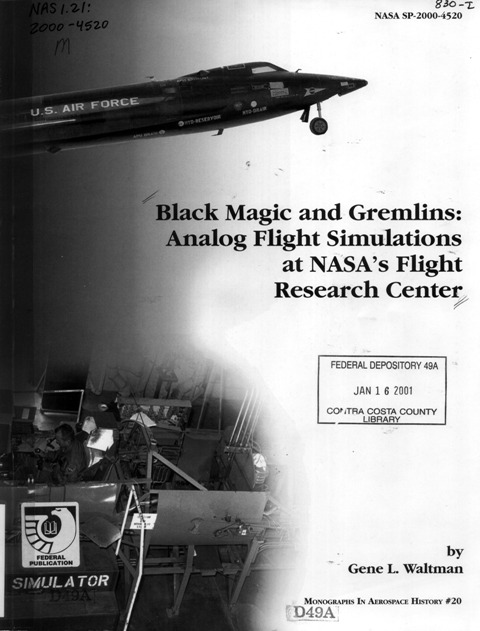
This is just not what you expect to find in a community public library. It's too techie. It covers about twenty years of flight simulation work by NASA in the 50's, 60's and 70's. This is simulation done with vacuum tube analog computers for the X-1, X-15 and lunar lander.
My earliest experiences with electronics were projects using parts salvaged from discarded vacuum tube television sets. (A few of the projects actually worked.) Later, in college, I did some limited work with solid state analog computers. I have some appreciation of what the NASA guys were working with, and against.
Unquestionably, the consumer flight simulation applications of today produce much prettier pictures and can support a much broader range of A/C system simulation. But I wouldn't be surprised to find that the analog flight model simulations were more accurate. Those NASA guys were real wizards.
Pedal Chapter in Draft, AVSIM Presentation Maybe (24 June 2007)
The Pedal chapter is now in reasonably good shape. I consider it a good draft. I'll let it sit for awhile then good back through it. I think it might benefit from an additional illustration or two, but we shall see.
The annual AVSIM convention is being held near Seattle in November. I'm considering making a presentation on tying physical switches into FSX. Of course, they haven't put out the call for papers yet. I haven't written one, and they haven't accepted my unmade offer. So, there's a little uncertainty.
"Last" Pedals Chapter Illustration (16 June 2007)
Writing is like building a sim. Neither is really ever done. In theory, I'm working on the last illustration for the Pedals chapter. Who knows, maybe it actually is.
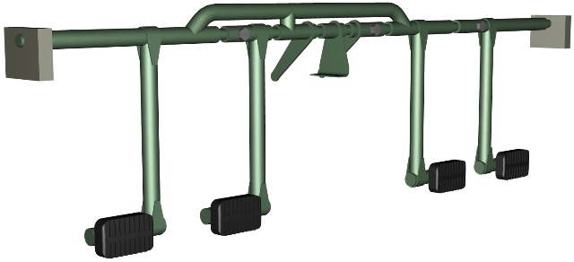
Anyway, here's a 3D image based on the model I built for developing the illustration.

The finished illustration for the book will be a line drawing. I find that building a 3D model helps me find the right perspective angle. Once that's nailed down, I can move on to the final product.
Still Doodling (12 June 2007)
I'm slowly finishing the illustrations for the Pedals chapter. I don't have engineering drawings, so I'm working from random photos and rough illustrations from pilot manuals. My illustrations don't need to be dimensionally precise to show how pedal mechanisms in real aircraft operate, but they do need to be internally consistent and at least moderately proportionate. It's time consuming, but I'm making progress.
Email Address Update (6 June 2007)
Spam directed to the site.comments mailbox has gotten to be too much of a hassle, so I've replaced the account with
![]() .
.
"Site.comments" is now history.
Toe brakes? I don't got to draw no stinkin' toe brakes.
(With apologies to H. Bogart.)
Pedal Chapter (5 June 2007)
With the pedal project more or less completed (flight sim projects are never really finished), I've been working on the chapter that contains that project. Demonstrating a complete lack of imagination, I call this chapter "Pedals". It's one of the early chapters, coming right after "Joysticks" and "Yokes". (Two more titles that didn't strain my imagination.)
These are fairly basic chapters. Why? Well, because flight simulation as a hobby can be as involved and complex as you want it to be be. But if you're just getting started, you want the basic stuff explained. I figure the first part of the book is a good place to put it, and flight controls are a pretty basic part of the flight sim hobby.
So "Pedals" presents a lot of basic facts. It talks about rudder pedals and why there is (or isn't) a change in feel to them as airspeed changes. It talks about anti-torque pedals, and how they feel. It explains what toe brakes are. It also presents some examples from real aircraft. If you're a real do-it-yourself type, an outline of how real flight hardware is configured gives you a leg up on how to structure your own design. (Do you know how the left and right seat pedals are coupled in a small Piper? Or how Piper's approach differs from that taken by Cessna? Read "Pedals" and you will.)
"Pedals" also demonstrates a DIY-style construction technique using metal. If you don't consider yourself terribly handy building things and have avoided using metal, give it a try. The pedal project demonstrates that it is possible to build strong projects using readily available materials without welding and without owning a gazillion dollars worth of tools.
At least that's what the chapter is supposed to do. It's not quite done. I've got a solid draft which means I can make sense of it, but it may be a challenge for anyone else. Most of the illustrations are there which means I did the easy ones first. So I'm left with about half a dozen drawings to be done, and a fair amount of word smithing. The chapters may be "basic", but I'm finding that developing them is more complex that building a sim.
Here's a 3D model of some Bell pedals I built to help me prepare some of the line-art illustrations.

Pedal Project (20 May 2007)
The pedals seem to be working reasonably well. Now I get to move on to the less than exciting documentation phase. Specifically, I have to make drawings that are clear enough for someone else to make a set without having anyone nearby to ask questions of. Making drawings is not nearly as much fun as cutting metal. Sigh!
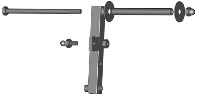
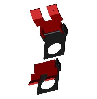
Although the illustrations in book 2 will be line drawings, I sometimes make shaded images just for fun. Here's an exploded view of one of the pedals.
On a slightly different subject, postage went up. The cost of mailing a book to domestic addresses rose by US$0.55 while the cost to most international addresses climbed by US$1.50. All things considered, air mail service to a substantial portion of the world is an amazing service, even at the higher cost.
Pedal Project (16 May 2007)
I feel a little like Goldilocks. The first attempt at damping was too soft. The second attempt at damping was too hard...
These are the second set of dampers I used. They're larger than the original set and much stiffer than I expected. Because they are larger, I mounted them differently on the pedals. ,,,,,, Actually, that's backwards. I planned on changing the mounting to gain a larger mechanical advantage for the dampers. Because of the different mounting I had to buy larger dampers. I needed units that could extend more, and that's what I got. I just didn't expect them to be so strong. I should have called the manufacturer and asked for better technical data. Instead, I swagged it based on incomplete data in the distributor's catalog.
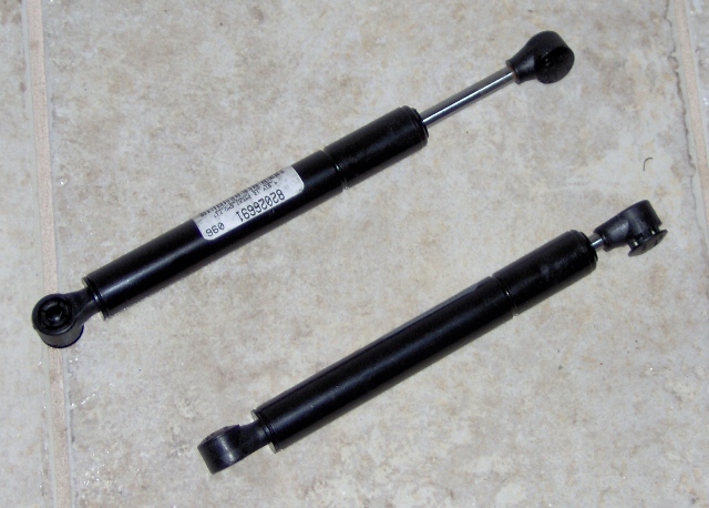
So, anyway, on to Goldilocks' third try. I went back to using the original dampers, but mounted them differently. And now, the damping is just right.

I'm now working on mounting a position sensor (high tech speak for potentiometer). I could use a slide pot, but my preference is for a high grade rotary pot. They last much longer.
I'm also toying with some ideas for toe brakes. Yes, I know, Jet Rangers don't typically have wheels, but some other helicopters do.
["SWAG" = scientific wild ass guess]
Pedal Project (10 May 2007)
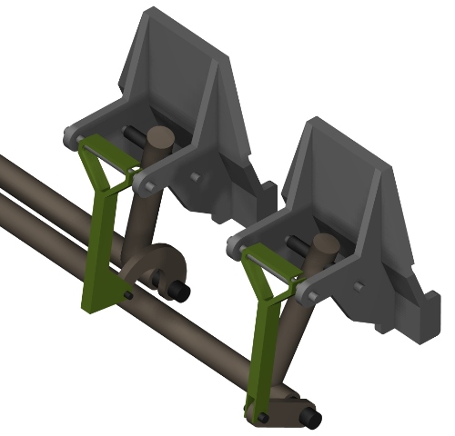
This project is more mechanical than those I've been working on recently, but don't accuse me of going steampunk. These aren't clank replacement parts or even flight controls for one of Baron Wulfenbach's dirigibles. This is the prototype for a set of anti-torque pedals based on those in a Bell 206B. (To reduce complexity, I've dropped the adjustment knob.)
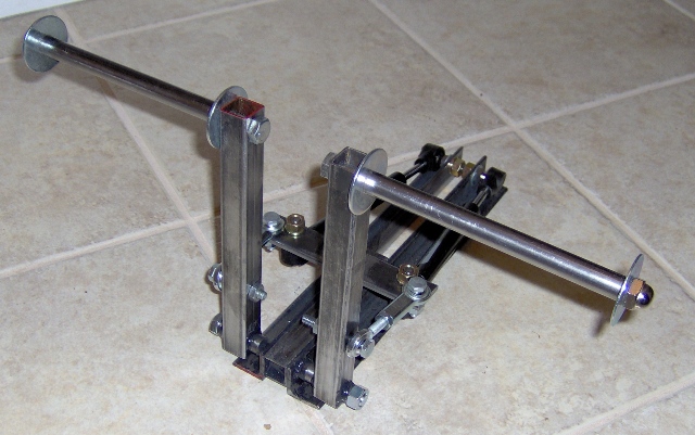
Most materials came from a local hardware store. A few items I bought through the web site of MSC Industrial Supply Co. All were easily obtained. Steel is used throughout, but there is no welding involved. Clearly, there are a few bolts in evidence, but I've also used epoxy. Stress is carried through metal-to-metal contact. The epoxy serves to hold the pieces in alignment rather than carry any significant load. It was built with basic hand tools and a bench top drill press. The result is a robust assembly that can tolerate heavy foot action.
The design incorporates a pair of hydraulic dampers to provide a bit of control loading. They improve the feel of the pedals, but I'm not quite satisfied. The damping is too light and I don't get a smooth feel from them. Even though they feel quite strong when pushed by hand, the mechanical advantage of the pedal lever substantially reduces their effect. Also the horizontal positioning allows gas bubbles to pass through the damping orifices, hence the not very smooth feel. Ideally, only oil should pass through. The fix is to reposition the dampers and to use heavier ones. They're on order.
Edited, Tested, Working (27 April 2007)
The testing paid off. There were a few minor errors in the C++ test program. The firmware revisions were correct as written, though it took me several hours to figure that out. At first it looked very much like the firmware was wacko. I'd made a number of changes, and it seemed quite reasonable that it not work. Turns out the prototype hardware had been built with a 12 MHz resonator for the PIC micro controller. The chapter calls for a 20 MHz resonator and the firmware configured the serial link bit rate generator assuming 20 MHz. With a 12 MHz unit, the serial link didn't work. Once I figured that out and put a 20 MHz resonator in, things looked much brighter.
I'll give the chapter one more read through then move on to a couple of flight control projects.
I had originally intended to introduce mold making and plastic resin casting as a means to make replacements for hard to find knobs. I've decided, instead, on a more ambitious project: making flight grips. As more people enter the sim building hobby, there is wider interest in different sorts of aircraft. In many cases it's impossible to find a realistic flight grip for a chosen aircraft. Most game controller joysticks are total fantasies. Don't get me wrong. There is nothing wrong with fantasies (some of my best friends are fantasies!), but if you want to build a realistic Cobra gunship, you want a Cobra flight grip.
As it turns out, you can buy a Cobra grip, albeit not cheaply. But there are many other styles that you cannot. So the project will cover making a wood and polyester pattern, a silicone mold, and casting a two part grip.
I also have some thoughts regarding non-welded, metal pedals.
Still Editing, but Soon Some (Re)Testing (12 April 2007)
The 54 page Using Real Instruments chapter has grown to 64 pages. There is now (IMHO) a much better description of how the project firmware functions. There's a new flowchart with names and labels that actually correspond with names and labels in the firmware listing. The firmware itself has been substantially revamped, and it might even work! There is a simple C++ test program for pumping test data to the project. I think it might work, too!
I suppose I really should test all this stuff.
That means I have to dig through that pile of stuff against the wall and see if my workbench is still there.
Sigh.
Just Editing (6 April 2007)
Well, the Switch Inputs chapter is "complete". That's not to say it's ready to go to press. It has to ferment for a while then I'll go back and edit it a bit. Or many a lot.
That's what I'm currently doing with the Using Real Instruments chapter, editing. Mostly it's minor stuff. A drawing refers to something one way while the text uses another term. Makes perfect sense if you already know the material, but can be monstrously confusing if you don't. In technical writing, this is a real no-no. It's pretty easy to fix.
There are a few larger edits needed, however. I changed the order of a few chapters. There's a section in what's now a later chapter that should be in what's become the earlier chapter. I've got a big chunk of text to move and modify for its new context.
Not very flashy, but progress nonetheless.
These Are Easier! (2 April 2007)
One Reason Books Take So Long (1 April 2007) (and this is no joke!)
This is your basic MS25224 switch guard. It looks innocent enough, but it's being totally uncooperative.
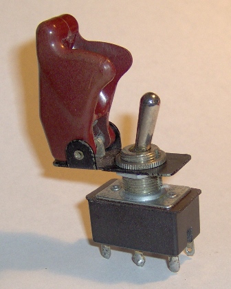
I'm finishing up the Switch Inputs chapter. The last (known) illustration is a collection of line drawings about switch guards. Switch guards aren't absolutely necessary, but they're a very nice touch. after all, part of creating a high fidelity flight illusion in a simulator is having good detail. It just wouldn't be right to have a Bell 206B sim and not have a guard on the fuel shutoff switch, now would it? And how about the munitions switch guards in an F-16 Falcon? Leave'm out? I think not!
So, any reasonable book about building home flight simulators simply must point out the importance of good detail and provide examples and illustrations. The problem is that the MS25224 modeling for the last illustration has too many rounded edges and I'm having a heck of a time producing a nice looking drawing.
Don't blame me for book 2 taking so long. It's the damn switch guard's fault.
LCD Radio Head & A Book 2 Milestone (22 March 2007)
The prototype LCD Radio Head project is together and working. There were some minor problems getting it talking to the serial port. The power connection to the data transceiver had been left off the PC board, and the connections from the transceiver to the data cable connector had been scrambled. The amazing thing was that the receiver portion of the chip was limping along well enough that test commands were getting through to the radio head PIC micro controller. I had one of the differential inputs connected properly and the other must have been floating at just the right level. I speculate that the chip was receiving power from an input pin through a parasitic diode. (EE hand waving. I don't really know why it worked.) In any case, once power was properly applied and the wiring to the connector straightened out, the PIC and my computer were able to talk.
Book 2 has passed a milestone of sorts. The manuscript is now bigger than the first book, Building Simulated Aircraft Instrumentation. The manuscript is at 420 pages and still growing. One reason is that book 2 has a broader scope. The first book focused on instruments. Book 2 covers the breadth of the home flight deck building hobby. I'm not covering it with the same depth as I covered instruments. There isn't enough room in a single book. I'm nonetheless covering the essentials for creating a high fidelity flight simulation experience, and that's turning out to be a lot of material. To make sure the information is useful, I'm presenting tested projects with drawings, flowcharts, heavily commented firmware listings and sample test programs. The pages are adding up.
D'ohhhh (16 March 2007)
Back when I was an undergraduate engineering student I discovered that integrated circuits work better when power is applied to the power pin.
Apparently that is still true.
A Little More Progress (15 March 2007)
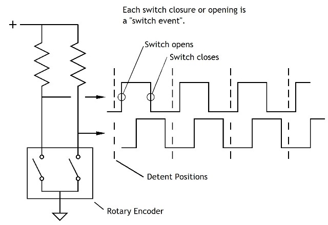
I got the rotary encoder hooked up and working on the radio head project. This is the second project in the switch inputs chapter of an upcoming book on DIY flight simulators. The first project highlights getting toggle-switch (or BCD thumb wheel) action into your sim. This project highlights rotary encoders and, as a bonus, LCD character displays. I still have additional testing to do, but so far everything seems to be working fine.
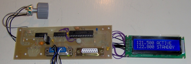
If the encoder is turned at a moderate rate, the standby frequency increments or decrements by .025. If it's turned faster, the step size jumps to .100. I may change that to .200. Haven't decided.
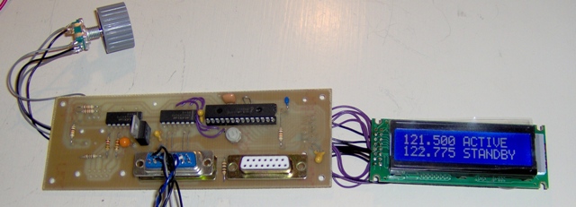
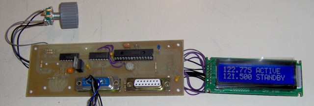
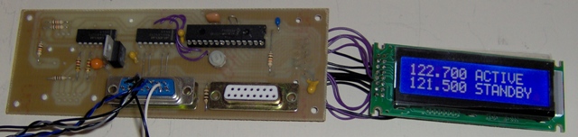
And if you push in on the encoder shaft, you trigger a momentary contact switch that swaps the active and standby frequencies, and sends a message to the host PC.
The next steps are to verify that the messages being sent to the host are correct, and to make a nice looking radio head panel. That should get me to the point of actually being able to do more writing on book 2.
A Little Progress (12 March 2007)
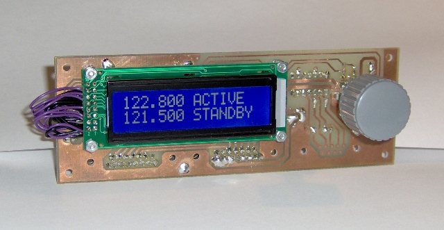
I got the PIC talking to the LCD module. It's a nice little module, especially as I only paid US$6.79. I bought it through Ebay from 411 Technology Systems. It was among the least expensive, new back-lit LCD modules I've seen. I'm pleased with it.
The LCD is displaying what was loaded into it by the PIC's power on reset code. At this point there's no communication with the host PC. The com code's in the PIC, but I've yet to add the code that bridges between the com code and LCD routine. The data com connector is just plugged in to provide power.
The next step is adding support for the rotary encoder. I've used encoders without detents in the past. This time I'm using one that has detents. The firmware will be a little different. The detents are located at each full grey-cycle. This means there will be four switch events for each detent. I only want to increment or decrement the frequency at a detent, so the code has to look for a sequence of four switch events before tweaking the frequency.
And if you're wondering about the choice of frequencies the LCD powers up with, I'm a (not current) private pilot who is used to non-controlled fields.
LCD Nav Comm Radio Head Project (9 March 2007)
The second project for the Switch Input chapter of book 2 is a Nav Comm radio head based on an LCD character display. One of the goals of the book is to introduce a variety of techniques that can be used in home built simulators. This project introduces rotary encoders and LCD character displays. Rotary encoders are very versatile rotary switches that interface well to micro processors. They take a bit of explanation, so I'll go into them in detail.
LCD displays don't have a whole lot to do with switches, so maybe shouldn't be part of the Switch Input chapter, but, hey, it's part of the project, so consider it a bonus. Considering how much utility you get for a few dollars for a display, it's worth knowing how to use them. The neat thing is, a great many LCD character displays use the same sort of controller. Once you know how to use one display, you know how to use just about all of them. I've got one line, two line and four line displays shown in the picture below. You talk to each of them using the same command set.
I'm using an inexpensive mechanical rotary encoder I picked up through Ebay. It has a momentary push switch built in as well. Actually, everything in this project is inexpensive. The PIC micro controller costs about $7. The two other chips are communications chips that run $3 or so each. There's not a lot invested here, but it provides some real utility. Turn the encoder and the standby frequency goes up or down. Push in on the encoder shaft and the standby frequency is swapped with the active frequency. The PIC can be polled for its frequency settings, or can be enabled to send a message to the host PC when there is a change in frequency. Communication takes place over the same RS-422 connection covered in the last rant.

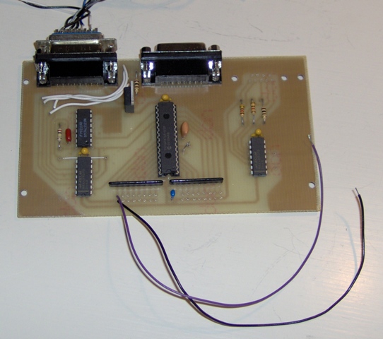
I stuck the rotary encoder on the chip side of the board to take this picture. It actually goes on the other side next to where the LCD module will be. The chips and the connectors will become the back of the finished project. I'll make a photogenic faceplate for the front. The board is two inches wide, so the project will look like a general aviation radio unit. I plan on using the two line LCD for this project, top line for active frequency, bottom for standby. Actually, the circuit could talk with any of them.
The next steps are to solder a last few wires in place and start writing some PIC assembly code.
Switch Interface Prototype and SimConnect with Delphi (2 March 2007)
I built the prototype for the first project in the Switch Input chapter of book 2. It interfaces 16 SPST switches to a PC through a serial port. It's a simple project, a PIC16F876A, a few communication chips and a voltage regulator. I considered adding more features like using a scanned matrix input mode so that it would interface 64 switches. However, some time ago I received some good advice that simpler is better, so I resisted. The result is a clean little module that you can use in a variety of applications.
You can use it to interface landing light switches, landing gear levers, master switches, starter switches, and so on. You can also use it for rotary switches. If you use BCD encoded rotary switches, a 10 position rotary switch only uses four input bits, so you could use this card as the basis of a transponder. If you were willing to modify the firmware, you could use this card to interface eight grey-code rotary encoders. (That's one of the features I did not add. I cover rotary encoders and LCDs in the second project.)
"But what do I do if I want to add more than 16 switches", you ask? "After all", you say, "a serial com port can only connect to a single device at a time".
I'm glad you asked.
This interface uses a party line connection called RS-422. It allows multiple devices to share the same connection. That's why there are two connectors on the prototype: data in & data out. You can daisy-chain these devices. RS-422 is also very noise resistant, and is quite happy with long cable runs. An inexpensive RS-422 adapter is needed to convert the PC serial com port from its native RS-232C to RS422. You can buy one, or flip to the Hardware I/O Options chapter and build the one described there.
You need a little more than just a party line connection. You also need a means to keep more than one device trying to talk at any given time. One approach is to poll the devices and only let them send data when allowed. This works well for small numbers of devices. With larger numbers the workload on the PC grows and the average delay before a switch is acted on by the PC increases. A second approach uses an arbitration scheme that requires a device to ask permission to send data. Clearly this has to happen outside the data channel being arbitrated, so it requires a tiny bit more hardware.
Specifically, it requires a separate arbiter circuit. It's really simple. It's just a PIC16F876A running a loop checking each device, ONE AT A TIME, if it has data to send. If so, it lets the device send. It waits until it's done before checking the next.
If you take another look at the picture above, the right most chip is there to send a request to send data, and to receive a grant to send. The prototype doesn't yet have the connector installed for the request/grant lines.
The arbiter handles eight request lines. If you build a very complex simulator and outgrow the limitation of just eight input devices, you can stack arbiters. It's a very modular approach. Just build the pieces as you need them.
I got a note from Scott Hendry. He's building an impressive Baron 58 simulator. He built some outstanding simulated instruments (a subject near and dear to my heart) and has a good start on a very realistic Baron cabin. But perhaps of wider interest is the progress he's made with Delphi and SimConnect. He and his compatriots have developed a set of Delphi header files for use in interfacing with MS Flight Simulator X. These header files, along with example programs, are available from Scott's site. Thanks, Scott.
Getting Switch Action Into a Sim (24 Feb 2007)
Switches don't occupy a huge part of your attention when you're in a sim. True, you tune radios and operate the landing gear, but most of your interaction with the sim takes place through the flight and engine controls, the instruments and the through-the-window view. The magic of having switches in a sim is that they let you remove the mouse and keyboard, two major detractors from the flight illusion.
For the past few weeks I've been working on getting switch action into a simulation computer. There are a number of interfaces you can buy, but of course I'm more interested in DIY solutions. It's easy to use a $7 PIC16F876A to scan an 8 by 8 array of switches and signal changes to the PC through the serial port. It gets a little more involved when you have multiple devices talking to the PC, but not seriously so.
I'm a big fan of the serial com port. There's no question that USB is a technologically more advanced interface, but from a practical, hobbyist point of view it's hard to beat the serial port. It's easy to access from a user program. It's inexpensive to use. It's robust and offers respectable bandwidth.
A shortcoming of the serial port is that it's based on RS-232C, a point to point signaling protocol. You can only hang one (bi-directional) device on a serial port. Sims tend to have lots of devices, and I'm reluctant to stuff my PC with lots of serial port expansion modules. A better solution to this sim-related shortcoming is to use a converter to change the RS-232C protocol to a party line protocol like the full-duplex RS-422.
A small sim might have a collection of random switches (master, avionics power, landing gear, starter, etc.), a nav/comm radio head and a transponder. I could build a single large module including everything that interfaced through a single RS-232C serial port, but using an RS-422 adapter allows me to build separate modules. That's easier and lets me add modules as I build them.
RS-422 provides versatility, but there's a potential problem. With any kind of party line system, the potential exists for more than one party trying to talk at the same time. When this happens data gets lost. There are several ways to deal with this.
One approach is to do nothing preventative. Simply look for an indication that the problem occurred and take corrective action as needed. This is not a bad solution in some cases. It's rare that one person in a basic sim will be using more than one switch at any given time. But what happens as the sim grows in complexity, as home projects tend to do? There is no guaranty that other, more gregarious devices might not need to share the RS-422 connection. We might then need an unacceptably large chunk of resources to take corrective action.
Another approach is to give the host PC the role of traffic cop. It can poll each device periodically. No one talks until asked to speak. Well, this works, but carries an overhead. It uses processor time as well as a portion of the port's output bandwidth. Further, it adds latency. As more devices are added to the group, there is an increased average time before the computer appears to respond to the switch action. For some things, like landing gear, this isn't a problem. For others, like radio tuning, it can be a major annoyance.
A more efficient approach is to require a device to ask permission before sending data. The request doesn't have to go to the PC. It can be handled by a dedicated micro controller using dedicated request/grant links. A requesting device can be granted permission usually within tens of micro seconds, so latency is minimal.
I have these projects designed. The firmware assembles. Next step is to build.
FSX Data Output with SimConnect (4 Feb 2007)
SimConnect is a utility that ships with the deluxe version of Microsoft Flight Simulator X. It allows programs to interact with FSX in a great many ways. The SimConnect programming interface consists of several dozen functions. A few of those functions relate specifically to getting data into and out of FSX. This is a great boon to us flight deck builders. (Thank you, Microsoft.)
The FSX Deluxe installation DVD includes an SDK for SimConnect that contains documentation and code examples. But while SimConnect is documented, it's not necessarily explained with the casual programmer in mind. A fair amount of background knowledge is (not unreasonably) assumed. Learning how to use SimConnect can require a bit of exploration and research.
That's what I'm up to these days, exploring and researching.
In particular, I've recently been looking into how SimConnect tells your program that new data is available.
By way of background, you get data from FSX through SimConnect by telling SimConnect the names of the FSX data you're interested in then telling it under what conditions to collect that data. However, SimConnect doesn't actually send you the data until you ask for it.
The question is, when should you ask for the data?
Most of the examples in the SimConnect SDK using polling. There is a loop that continually calls SimConnect_CallDispatch(). This is similar to a kid in the back seat of your car asking "Arewethereyet?Arewethereyet?Arewethereyet?Arewethereyet?..."
It's not actually that bad. The CallDispatch() call is followed by a Sleep(1) statement. When the operating system gives this piece of code its time slice, one call to CallDispatch() goes out and the code releases the remainder of its time slice. The "1" parameter tells the operating system not to wake it up for at least 1 millisecond. If you've set up the data collection to happen at the end of each FS frame and you're getting 20 frames per second, you're making 50 calls to get the data sent.
So you're making 49 calls to CallDispatch() that aren't needed, and that wastes system resources that could be boosting your frame rate. Well, sort of. In the grand scheme of things that's not really a lot of waste. You're not actually making SimConnect do much, you're simply setting a flag that tells SimConnect you're ready to receive data. Still, the call does result in a context swap, and maybe you have a lot of separate connections to SimConnect ALL beating on it for data. You might then begin to incur some serious waste.
The alternative to polling is to have SimConnect tell your program when it has the data ready. There are two ways to do this. One makes use of the Windows messaging system. When you first open the SimConnect connection you can give SimConnect a handle to your window and a message to send to you. When the data structure you requested is ready, SimConnect sends your window procedure the message. You then call CallDispatch() to collect the data. Of course you have to have a window to use the messaging system. You can set up a bare bones window for this purpose, but if you wouldn't otherwise use a window you can use an event instead of the Windows messaging system.
An event is a flag that is set up by a program and maintained by the operating system. It is accessed through a handle and can be set and cleared. It's used to synchronize execution between different threads or programs. You create an event using the CreateEvent() call. If you pass the event handle to SimConnect when you first open the SimConnect connection, SimConnect will set the event when data is available. You can use the Windows function WaitForSingleObject() in your program to synchronize its execution with the availability of data.
I'm finally getting to a point that I can almost write the "Interfacing with MSFS" chapter of my upcoming book, Building A Recreational Flight Simulator. Not surprisingly, SimConnect figures prominently in it.
Scenery Display & FSX Data Output with SimConnect (25 Jan 2007)
After my visit with Tap Plastics a few weeks ago I got interested in the optics behind scenery display systems again. It's an interest that pops up fairly frequently, but I usually don't have the time to make much progress. This time I used two new tools.
The first, geometrical ray tracing, isn't really new, it's just new to me. Based on a few reasonable simplifications to how mirrors and lenses deflect light, it allows you to gain a basic understanding of how an optical system behaves. Armed with this deceptively simple tool, I turned my sights on a basic mirror collimated display. Lo and Behold, things began to make sense. I had read the words before concerning what a collimated display did, but I was finally able to tie it back to a couple of proprioceptive depth clues.
I also took a closer look at using Fresnel lenses in front of monitors. I had always been confused by the range of comments posted by supporters and detractors. Why the difference, and what was really going on? Well, I think I have a better grasp on that as well. A lens (Fresnel or otherwise) can be used to enlarge the apparent size of a monitor. If you position the lens to magnify the image a great deal, you also produce significant (and to my taste, unacceptable) geometric and chromatic distortion, particularly around the edges. Moderate magnification results in some arguably acceptable distortion. With moderate magnification, you can blend the images from adjacent monitors into a continuous panoramic view. With a single monitor, a lens allows you move the monitor away from your point of view and maintain the same apparent image size. For some people, having the image farther away allows the depth clues embedded in the image to be more effective. I think Fresnel lenses are useful in some situations but are no panacea.
The second tool is new. It's Google's Beta patent search. There is an incredible wealth of information in patents. Yes, I know it's been possible to search patents on line for several years. IMHO, the user interfaces have been a real pain in the backside. Google makes it easy. Okay, I'll admit it would be nicer if the patents weren't presented as image data, but I can live with it. Anywho, a few searches on "simulator display", "collimated display", etc. and all sorts of interesting material pops up. With a little patience you get a good look at the history and technology behind simulator display systems.
Of course, as I had put all this effort into the topic, I dropped my foray into modern day programming self-education and cranked out a draft of the chapter on simulator display systems.
I did mange to spend a little time with FSX. (I emphasize the word little.) I got a very basic data output example limping along. Mostly, it pointed out a shortcoming in another project with the result that I had to do a bit more micro controller assembly debugging.
Acrylic Mirrors, FSX Data Output & The REAL Programming Problem with Memory Leaks (5 Jan 2007)
First of all, the best of New Years to everyone.
Acrylic Mirrors
I just came back for a very informative and pleasant trip to my local Tap Plastics. I had some questions about heat forming mirrored acrylic. I specifically wanted to know if the mirror backing would come off when heated and, if not, how far it could be bent before it did. The person I asked said he didn't know but would find out. I watched as he heated a fairly large "scrap" of mirrored acrylic and proceeded to bend it back and forth with no separation of the mirror backing at all! I was very impressed with both the mirrored acrylic AND with the level of customer service of Tap Plastics.
Why the interest in plastic mirrors? Well, curved mirrors are central to many panoramic display systems. Professional flight simulators make use of flexible mylar membrane mirrors that are held in shape by a partial vacuum behind them. These are simple in concept but quite difficult in the execution. I recall heat forming of acrylic as junior high school shop projects (a very long time ago). I wondered if it would be possible to make a curved mirror suitable for sim use by thermo-forming mirrored acrylic. Hence the trip to Tap Plastics.
I don't have a definitive answer as yet, but so far it looks feasible.
Getting Data From FSX
I continue to explore SimConnect. The SDK contains a number of code samples that highlight various SimConnect functions. A very helpful sample is the "Request Data" example. It waits for a flight to start then asks for a few bits of data on the aircraft. It works great and has been easy to modify to continually extract a variety of data.
I've also been re-creating the basic test code I used when developing the prototype instruments for the book Building Simulated Aircraft Instrumentation. I originally wrote the code using VC++ version 5. My attempt to recompile it using VC++ .NET Express Edition didn't work too well. (Crashed and burned, in fact.) I now have a very basic program that sends incrementing numbers to the dual gauge LED instrument project (See notes from 4 Dec 2006).
So, I now have the two halves to the FSX data output demo program that goes into book 2. Just have to glue them together. It's always a hoot when the pieces come together and things start working the way they're supposed to.
Programming Memory Leaks
Memory leaks are generally considered to be programming problems associated with improperly releasing computer memory. This occurs when a program dynamically asks for and is allocated additional memory, but loses track of when it is no longer needed. A program that runs long enough can accumulate enough memory that it squeezes other applications out, causes itself to be shut down and/or crashes the operating system.
There is, however, a more insidious memory leak, a biological leak.
It happens, oh, perhaps in your late fifties, when you realize you're working through your fourth, fifth, sixth(?) intro programming book. The stuff goes in, but some of it leaks out! Getting old sucks, but I guess they're right. It's better than the alternative!